I'm going to talk a bit about my friend Frankie's car. It is a 2002 Mustang GT. He called me up and asked me what was involved in replacing (and upgrading) all four calipers, rotors and brake pads. I did some research and came up with a few options. The 14 inch s197 caliper upgrade in the front, cobra upgrade front and rear, big brake setup, etc. His reply was pretty simple - What about the kit from power stop? I hadn't heard of it. The part number he gave me was KC1302-26. I looked it up on rock auto. The price point was NICE! and they were offering a discount code if you bought the kit in October. The kit is 520$ from rock auto, with a 100$ core charge. That puts the final cost at 418$. Not bad for 4 re-manufactured calipers, brake pads front and back and rotors! The calipers are also powder coated. It seemed like a sweet deal! I also advised him to get the Russel stainless steel braided brake lines. Since we had to remove the calipers anyway, this was just one more step and a nice upgrade to the pedal feel.
Frankie showed up at my house on Saturday morning ready to go. I started working on the front drivers side while he was working on the back drivers side. I removed the caliper bolts, hung the caliper and removed the rotor. I hit the new rotor with brake clean, then put it on the spindle with a lug nut to hold it in place. I made sure the new caliper had the correct hardware. The caliper bracket was already installed so we installed the pads in the caliper. Next up was the brake line. I disconnected the line from the caliper. It immediately started dripping - so be ready to catch the fluid or it's going to make a mess. I put the old caliper off to the side. Using flare wrenches, I removed the factory brake line from the hard line. As I tried to remove the banjo bolt from the stock line, I realized that the crush washers wouldn't come off. We needed to reuse that banjo bolt. We had to use pliers to hold those washers in place and spun the banjo bolt to back it out of the washers. New washers came with the SS Braided line kit. I installed the new braided line onto the hard line and tightened it and secured it. Next I installed the banjo bolt with new washers onto the new caliper. Then installed the caliper on the rotor and tightened the caliper bolts. The first wheel was done!
In the meantime, Frankie was fighting with the rear caliper. The emergency brake cable is a pain to disconnect. It really requires two people. One to compress the spring, and the other to actually remove the cable from the spring. I guess thinking back that we could have used vice grips or a clamp to hold that spring, especially if only one person was working on it. We got it disconnected after a few select words of encouragement. What I didn't realize is that with everything disconnected, including the factory line, the brake fluid was dripping for a good long while. When he was stuck with that drivers side caliper emergency brake cable, he moved to the passenger side and disconnected that caliper. I left Frankie to keep working on it and I moved to the passenger side front caliper. The procedure was the same as the front drivers side.
By the time I finished the front drivers side, I moved to help with the other emergency brake cable. Then we started the re-assembly. We found out right away that the powder coating was also inside the hole where the emergency brake cable sits. It was way too tight and we couldn't get the cable in there. We needed to remove the powder coating with a dremel and then we were able to install the cable. We did get the emergency brake cables installed, but not the stainless braided lines yet. Frankie got a call, and had to run an errand. Since his car was down, my wife and I drove him. He finished what he had to do after a few hours and we headed out to get something to eat. When we got back to the house, we picked up where we left off. I noticed right away that there was no more dripping fluid. I said - this is going to be bad, we shouldn't have let the system go dry. He gave me the look like "what could possibly go wrong?".
I forgot to mention that the rear rotors did not want to come off. I have a neat trick for this. I got a bolt and put it through the caliper bolt hole On the inside, between the rotor and the caliper bolt hole, I threaded the bolt into a nut. Then with a wrench on the nut to hold it in place, I tightened the bolt with a ratchet. This eventually puts pressure on the rotor, trying to push it off. Sometimes it pops the rotor free, other times I just need to hit the face of the rotor on the opposite side of where the bolt is. A pretty firm hit with a dead blow hammer usually does the trick.
We installed the new rear rotors with a lug to hold them in place. The best way to do the rear caliper install is to install the caliper bracket, then the pads (with hardware) into the bracket. Remember, the emergency brake cables are already installed on the calipers. Then we installed the caliper onto the bracket. We needed to push down and hold it in place to get the bolts for the pins installed. The last step was to install the SS braided lines. We remove the old ones from the hard line, along with the bracket. Then we installed them with the new crush washers and the old banjo bolts. I learned that its a good idea to leave them loose at the hard line until you get the correct orientation. Then once everything is in place, tighten it up.
The last step was to bleed the brakes. Frankie sat in the car while I went around wheel to wheel cracking and closing the bleeder. Finally, after a few hours, we were getting clear fluid at all four corners. The problem was that there was still NO firm pedal. It went straight to the floor. We did fix some leaks at the hard lines and banjo bolts while we were doing the bleeding. It is REALLY easy to strip the fittings. So if the fitting leaks, tighten it just a little more and repeat until the leak is gone. It was time to call it a night. We were whooped. We would get after it again tomorrow.
After some research and a post to FB about the no pedal issue, a few suggestions were made. 1 - someone noticed that the bleeders for the front calipers were on the bottom, which means that the front calipers were on the the wrong sides. The bleeders need to be on the top of the caliper because air rises. We needed to swap the front calipers. Note - they were labeled incorrectly - never trust the labeling. 2 - The fact that the system dripped for so long meant that the master cylinder could be an issue. The extended travel could have blown out the seals in the master cylinder. Frankie ordered a new one just in case, it would arrive Wednesday. 3 - The master cylinder may need to be bench bled. We decided to wait to get the new master cylinder before removing the old one to bench bleed it. That way we could replace it if needed.
Frankie arrived again on Sunday and we swapped the calipers and installed them again. Back to bleeding for a good long time. Some air did come out, but still no pedal. We decided to put the wheels back on and re-group on Wednesday. Monday came and went. Tuesday I was talking to a colleague at work who is also into mustangs. After some discussion and some research, we found that bleeding the master is MUCH easier than on the older cars. The
older design meant that the master had to be removed from the car and
bench bled. The newer master cylinders have bleeder screws on the side
of the cylinder itself. No need to remove it! When I got home Tuesday night, I was telling my wife what we found. She said - we should try it, sounds simple enough! So we headed out. She sat in the car and worked the pedal while I bled the master cylinder. First time she held pressure on the pedal and I cracked that bleeder, a bunch of air came out. We did the same thing again and the pedal seemed firmer! I moved to the other bleeder and the pedal was firm. We repeated the process a few times to make sure we got all the air out. I called Frankie to tell him the good news.
Frankie showed up on Wednesday and we went out to bed the brake pads and new rotors. After the process was done, we noticed that there was some fluid on the inside of the wheels, likely from the banjo bolts not being tight enough. I offered to take it in again and fix it, but he needed to go and said he would do it once he got home. A day or two later he called me and told me that the leaks were fixed! He also told me that there is a torque spec for the banjo bolts. He said the brakes feel great and were getting more aggressive as he drove the car.
I'm glad we were able to finally get it all figured out. Lesson learned - never let the system drip dry as it causes the need to bleed the master and all four calipers, which can take a long time. Also, don't trust the labeling on re-manufactured parts. Always put them side by side with the parts you are removing to make sure they are correct!
Monday, December 5, 2016
Sunday, September 25, 2016
Motor Home For Sale
2006 Fleetwood Excursion 39L Class A
Good Condition $89,000
60,000 Diesel Miles
Everything works, upgrades & extras
Call Peter 732-800-2205
Serious buyers only please
2006 Fleetwood Excursion 39L Class A
Good Condition $89,000
60,000 Diesel Miles
Everything works, upgrades & extras
Call Peter 732-800-2205
Serious buyers only please


FEATURES: Directv satellite installed, 4 slides, dual zone A/C, CAT 350 pusher. Here is a link to the original flyer that outlines all the features: Fleetwood2006_excursion_b.pdf
EXTRAS: No smokers; no pets; professionally washed & waxed exterior & interior; road ready; ¾ full diesel fuel, ¾ full 40 gal. propane tank; color back-up camera; CB radio; permanently installed low voltage / surge protector; 4 new rear Goodyear tires 2015; 2 newer front Goodyear tires; Break Buddy & Stow Master 6,000 tow hitch & ball; generator exhaust extension; stainless steel propane BBQ grill; various spare parts (light bulbs, fuses, etc); Thousand Trails Membership available for sale separate.
Tuesday, August 30, 2016
1994 Mustang GT: Condenser and Radiator upgrade - In Traffic!
The ride in to work is about 74 miles. Early this morning, the weather was pretty nice. It was 65-70 degrees the entire way. Using my laptop, the Moates Quarterhorse and Binary Editor, I can monitor the exact ECT temp - along with a bunch of other parameters. Pulling the hills on Interstae 80 heading to Roseland NJ, I got the temp up to 190. I tried turning on the AC on max when it was 190, but the temp dropped to 186 very quickly. Needless to say, the ride in to work was uneventful. I checked for leaks when I got to the office and there were none.
For reference, heading to Myrtle Beach in July we were seeing 204 during normal driving with the AC off. Turn the AC on and that easily added 20 degrees. That was the stock setup.
I left work just before 4pm. I got to the car and turned on the laptop. Even before starting the car the ECT was 118 degrees. It was HOT under the hood after sitting in the sun in the parking lot! I started the car, fired up the laptop and started logging. Then I turned the AC on MAX. The ride started out well, and soon I hit the rush hour traffic. Back to school has a lot of people on the roads again. There are still a lot of hills, and it was stop and go traffic. I was driving the car normally, with the AC on max. I was even 'getting on it' a little going up the hills trying to see what the temp would peak at. The absolute max for ECT was 206. The ACT was also 134 at that time. So it was pretty hot sitting in traffic with all the other cars. As soon as the car started moving, the temp dropped. I kept the AC on the entire time, and never did any 'tricks' to try and drop the temperature. The ride home took almost 2 hours with the traffic due to accidents.
Eventually I had to stop for fuel. This was well after the traffic had let up. I fueled up, dropped the top and set back on my way home with the AC off. The battery on the laptop was slowly diminishing after all the logging on the way in and all the traffic, but it still had a little bit left. the temps sat right around 186-188 for the rest of the way. At least until the laptop battery had given up. I would say there was some 'spirited' driving, and the ECT stayed pretty consistent - high 180s low 190s with the AC off. It was a great day to test out the upgrades, and I couldn't be more pleased with how the car performed after the uprade!
Monday, August 29, 2016
1994 Mustang GT: Condenser and Radiator install
I had a leak in the suction / discharge line so I knew I was going to be doing some AC work. As you read in my other posts, I also had an overheating problem. I got the correct condenser - part numbers are in the other posting - a new 3 row champion radiator cc1488 and the correct suction discharge line. I also rented the vacuum pump from Autozone, and picked up 3 cans of refrigerant R134a from Walmart, which has it for sale for less than 5$ a can. That is a GREAT price.
Here's a neat story before I get to the installation write up. I ordered a champion 3 row from Amazon. Same day my friend says he has one used and cuts me a great deal on it. I was expecting to just return the unit to Amazon. Then the unit from amazon shows up POLISHED! I put the polished unit in and sold the used one for what I paid for it.
I started by draining the stock radiator. Then the CCRM bracket so I could get the overflow out. Then pulled the fan and radiator together. Lesson learned, I also removed the CCRM and put it aside so as not to knock it around. Next I pulled the condenser, and the suction discharge line from the compressor that was leaking. The lines are all similar to the fuel lines - so the fuel and AC disconnect tool works perfectly. The system didn't have any refrigerant in it due to the leak, so there was nothing to reclaim.
The stock condenser had some plastic pieces on it to direct the flow of air. They mounted to the condenser and made sure that the air didn't escape between the radiator and the condenser. Those pieces mounted to the stock condenser with push pins. I couldnt use them on the upgraded condenser, so I used some small black zip ties. The zip ties were able to be routed around the end 'tanks' of the condenser without hitting any fins. They did the job perfectly. I then installed the upgraded condenser, which fit in the factory location without any issues at all.
Next was the install of the stock fan shroud onto the new radiator. As you can see from the pictures, the fan didn't quite line up with the bungs on the radiator. I also had to re-tap the bungs since the bolts didn't thread in nicely. After running a tap through, they were fine. I got the left side lined perfectly, but the right side didn't really line up. I simply drilled a hole in the shroud mount and put the bolt through that hole.

You can see here that the stock condenser is really road weary from all the miles / years.

Here is the stock condenser on the right, and the upgraded unit on the left.

Here is the new suction discharge line side by side with the original.

The new radiator needed some persuasion to get it installed. The anti-lock break unit needed to be moved a bit. I loosened all the bolts, put a pry bar on it and tightened it back up again. Then the radiator was able to fit into the lower mounts. I also needed to move / and somewhat relocate the wire loom that runs across the upper rad support. The drivers side of the radiator, where the rad mount would go, was hitting / pinching that wire loom. Once I moved it down a bit, there was clearance. It was tight, but I was able to get the rad mounts installed on the top of the radiator. Then I put the overflow in the bottom hole, and realized that there's not much clearance due to the extra thickness of the radiator. I should have made a new mounting hole for the lower plate that the overflow mounts in, but I made it work. I installed the CCRM and mounted that bracket. It was really tight. There's also not a lot of space between the fan and the pulleys now.
Last up was the suction discharge line. I used some petroleum jelly on the O rings. Then mounted it to the compressor. That took some bending and modification of the line placement. After some time, I did get it to seat right into the compressor, and tightened down the mounting bolt. Lastly I connected all the refrigerant lines, which just press right in.
I hooked up my 134a gauges to the high and low side, and the center yellow line was hooked to the vacuum pump. I ran the pump, opened the high and low sides, and it pulled a vacum. I let it go for some time, then closed both sides, then shut off the compressor. I let it sit overnight to make sure there were no leaks. I missed a step here through - I should have pressurized the system with nitrogen and checked for leaks. Then pulled the vacuum again. I didn't have a nitrogen tank on hand ( and only learned about the nitrogen step later).
The next day I filled the radiator with fluid and pulled the car out. As it was warming up I put the AC on full and I charged the system. The first can of 134a almost gets sucked in due to the vacuum. The second can took a little longer, and finally the third can. By that time the car had warmed up, and the level of coolant in the radiator dropped. I topped it off, and put the cap on. I let it idle for about 10 more minutes, cleaned up some spillage, then took it for a ride.
I instantly noticed that the radiator is much more efficient. The temperature drops FAST when that thermostat opens up. And the AC is really cold. I do need a hot day in traffic to really test it out.
I had it out again today and checked again for leaks. Everything checked out OK! Tomorrow I'll take it into the office 150 mile round trip and then report back on how it does in traffic.
Tuesday, August 16, 2016
1994 Mustang GT Condenser Upgrade - Correct Condenser
I'm finally done doing the condenser dance. I bought 3 different condensers - one from Rock Auto, two from Amazon. All of which were NOT the correct aluminum upgraded fin design - see my previous blog post about that. Finally someone on the corral set me straight. The part number for the condenser I now have is: F7ZZ-19712-BA or YJ-396 or YJ396. The tag on the condenser where the lines connect is F7ZH-19D734-CB - but I think that part number is for the adapter. The adapter bolts to the condenser, and has the male fittings that connect to the lines. This would allow the condenser to be used on various year cars by changing that adapter.
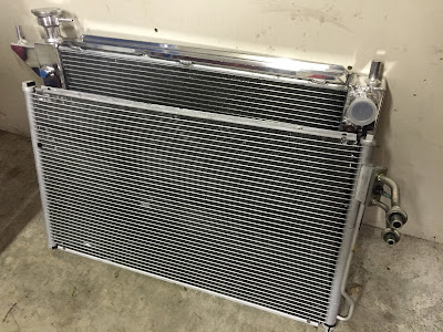
Here is a picture of the new CC1488 Radiator and the Condenser. Below is a close up of the adapter for the condenser.


I was able to rent the vacume pump from Autozone. Next step is to get started with the removal of the old parts and put in the new parts. Something always seems to come up though - Hopefully I can get to the installation soon!
Monday, August 1, 2016
1994 Mustang GT: A/C Condenser upgrade
The stock condenser is just that, a stock replacement. I wondered if there was a better design that came out for a later year mustang. Wouldn't you believe it, they did update the design! The condenser for a 1994 works for a 94, 95 and 96 v6. In 1996 the cobra had issues cooling. So when they released the 97 cobra, the SVT team decided to give a little more airflow to the radiator. They ditched the stock conventional condenser:

and went with a parallel flow, all aluminum condenser which looks a lot like the design of a radiator.

The 97 condenser should be the same exact size, so it will fit. The lines will need to be modified / bent a bit to make everything line up. From what I've read online, this should be very minor. Now, with that being said, I've already ordered a stock replacement from Rock Auto before I learned of the upgrade. As luck would have it, that showed up with some damage to it so it was returned. I also ordered what I thought was the Spectra upgraded aluminum parallel flow radiator from Amazon. When that showed up it looked exactly like the top picture. The part number is 7-4676 which is NOT the upgrade. So another return was issued for that condenser. Earlier today I ordered spectra 7-4962 which should be the upgrade. I'll let everyone know on Thursday 8/4/2016 if this is the right one. I also needed the suction / discharge line for the condenser since it leaks a bit. I plan on doing them both at the same time.
Since the stock radiator needs to be removed to install the condenser, I'm planning on upgrading that radiator to a champion cc1488 3 row aluminum radiator. I picked one up used with the dual fan setup, but I'm pretty sure the stock fan flows more. The dual fan setup from champion flows about 2000CFM. The stock SN95 fan flows 3-3800 CFM. And it's fairly new so I'm going to use that one for now. Stay tuned for more pictures and comparisons!
Wednesday, July 27, 2016
Mustang Week 2016
Last year we had some rubbing issues where the rear fenders would hit the tires. There was a 1 inch hubcentric spacer between the back wheels and the axel. That was removed and a 20mm spacer put in place. The other change is the MM weight jacker rear lower control arms ( see my suspension write up on those ). Just before loading the car up, I jacked the rear suspension by about 1.5 inches. There was NO rubbing on the way down. Maybe the Eibach pro kit with progressive springs also helped. As the car was loaded, and the rear spring perches increased, the springs were more compressed. Being a progressive spring, they responeded differently. All in all, it was a great drive down. When we got to the condo in Myrtle Beach and unloaded / unpacked, I dropped the suspension to a more reasonable ride height without all the weight. Before we left, I jacked it up again before we loaded it all up. It worked perfectly.
The next thing I learned was that the idle needs some work. I have since made some changes to the Quarterhorse calibration in Binary Editor after getting home. Turns out that I had the RPM for when idle routine was entered way too low, so most likely it never used those idle functions and scalars. I also had the desired idle set too low. After some reading I learned why the ECU cannot control idle lower than the current 900 rpm. Right now at 900 RPM the ISC duty cycle is 10% which means it's not moving at all because there is too much air entering the engine through the throttle body. I'll be doing a base idle reset soon. If I can get the duty cycle for the IAC around 15% then the computer can control idle, which would be ideal!
Next is the overheating. The past few years we have left for Myrtle Beach in the middle of the night. We travel through the night and arrive early in the morning. There's very little traffic and only minimal construction to deal with. This year we didn't do that. We traveled to see family near Richmond and stayed there for two nights. It was about 7.5 hours to my cousin's house. It was 5 hours down to Myrtle Beach. We left Richmond in the morning and got to MB during the peak of the day. I quickly learned that traveling during the day also meant that the hottest part of the day, and the peak of the sun, was going to have an impact on the coolant temp. The temp was high and I needed to turn off the AC periodically to let the car cool down. This was rough when we were in traffic. If we didn't turn off the AC, the car would overheat. Fast forward to the trip back on 7/24/2016 - there was a heat wave in the northeast. During normal driving the car would run at 204 degrees F. Once we turned on the AC, the temp jumped by at least 20 degrees.
Although the AC worked well, I know that there is a leak on the hose that runs above the drivers side headers. This is the 'manifold refrigerant hose'. I also inspected the condenser - which is what cools the 134a after the compressor. It is really beat up. I think it's original to the car. The fins are so bent over that I can't imagine it will let much air though it. My thought is to replace that condenser and the manifold line, use a vac pump and make sure there's no leaks, then charge the system again. I think that will remedy the cooling problem. Hopefully!
Another school of thought is to upgrade the radiator to a bigger unit. I have a stock replacement installed in the car right now. I needed to replace the original since it was leaking. Champion makes a 3 core all aluminum radiator:
All in all, the car was really comfortable to drive. The suspension worked well, the seats are comfortable and the new Gibson MWA mufflers all but eliminated the drone at cruising speed. I really enjoyed the seat time, even if it was for 1700+ miles. By the time we take this on another road trip, I'll have that calibration dialed in even more, and the cooling issue should be resolved.
Thursday, July 7, 2016
1994 Mustang GT: Vortech and Tremec
In most of my blogs you'll hear me reference 'my buddy' or 'my best friend'. That guy has always been by my side when it comes to anything mustang. He's been my groomsman more than once, and I've done the same for him, more than once. So when Lou called me up a few weeks ago and said 'I'm going to do you a SOLID' my ears perked up. He had come across a project car that someone wanted to get out of. The car had a bunch of stuff he wanted / needed and a few parts that I could use. Cash up front from me would mean that he didn't have to dive too far into his pockets to make it happen. Lets just say that the deal was very very good.
Fast forward to today, when there is a TKO 500 transmission sitting in my garage. Sitting next to it is the bell housing, fork, driveshaft spacer and on top is an MGW shifter with the handle. Also in the same area is a Vortech V3 Supercharger, an intercooler, two additional pulleys and a mondo bypass valve. There's also a mess of piping, couplers and clamps to go along with it. To say this was the deal of the year would be a complete understatement!!!
If you've been following along, you know that I've become very familiar with the Moates Quarterhorse and binary editor. I've been building the calibration in a way that it should accept a power adder with no problem. That portion of the calibration should essentially 'come alive' once boost is added. I've also just remedied the voltage drop between 4 and 6k RPM during a WOT acceleration. Voltage drops are not good for fuel pumps at all. Pumps want to see a constant 14v to perform adequately. Thats why Kenne Bell and Vortech created regulators that keep pump voltage constant under all conditions and even provide a way to increase pump output with a boost reference. I'm going to need to do some upgrades to accommodate the supercharger. The transmission installation should be much more kind.
Fuel System
I'm going to also include the Mass Air info here, because it is essentially what the calibration will use to determine fuel delivery. I currently have a 2004 F150 90mm mass air sensor installed in the car. The curve won't be enough for the additional air flow of a supercharger. Besides that, I would really like to use an 05+ mustang slot style mass air sensor in a blow through configuration. The piping is 3 inch and I'm not so sure that the curve is adequate. I may have to go with an HPX sensor, which has some pretty serious values for the transfer curve. More on this later!
I already have Siemens Deka 60lb/hr injectors installed. Stock fuel rails, a Kirban adjustable FPR, stock lines and a Walbro 255LPH in tank pump are installed as of today. The pump is not the high pressure / high volume pump. I did use Earls fittings on the stock rails to go to -6AN Fergola braided stainless line. They mate to Earls fittings on the hard lines on the firewall. Feed and return are both -6AN. The feed at the firewall is 5/16 and the return is smaller. See my blog about the fuel lines / fire hazard fix! What is interesting is that the fuel hat / hanger assembly has a 3/8 feed and a 5/16 return. I also know that the pump won't be enough. The plan is to upgrade to a Walbro 400LPH pump (Walbro 39/50 DCSS 400LPH F90000262). . This will also require that I upgrade the wiring to the pump. I'm going to run 10GA power wire from the battery, or a dedicated 12V source, to a 40A relay. I'll use the existing positive lead going to the pump for the signal wire to that relay. The output to the pump will be 12GA. I'll also have a 12GA ground wire going to the frame. That should ensure that the wiring can handle the draw of the bigger pump! The fuel rails shouldn't need to be upgraded. The fuel lines should also be good to 500HP, which I'll never see. Should is the key word. I may use a 3/8 to -6AN fitting for the feed line on the fuel hat and run a new 6AN line to the front where it meets the existing 6AN line via a union. Still undecided on that as well. Those are my thoughts on the fuel system.
Supercharger and intercooler
The supercharger is made for a 94 95 mustang, so the discharge is aimed at the throttle body. That doesn't leave much room for the bypass and blow through mass air meter when not using the intercooler. I also think that the intercooler I have is too big - its 4 inches thick, passenger inlet and drivers side outlet. There would be no way to take the output of the supercharger and run it to the intercooler and the output of the intercooler to the throttle body. There's just no room. What I would like to do is to exchange the v3 for a straight discharge head unit. Then we could run it into the fender to the intercooler and have the intercooler come back the same way. That would also require a same side inlet outlet intercooler. Its going to require a lot of fab work for the piping, but it would work! Someone even did it already, which gives me confidence. Here's the link to his ride: http://www.vortechsuperchargers.com/page.php?id=45341
Ideally, with some additional piping to the intercooler, I'll be able to set up the blow through MAF and a Blow Off Valve rather than a bypass. We shall see. More to come on this!
Transmission
When I pulled the transmission, I read the tag and it said TR3550. At that point I didn't think it was a TKO500 as the guy claimed it was. That would also be a 1k price difference. I was certainly disappointed. After I got the trans home, I tried to look up the part number on the TR3550 reference page to see the gear ratios and couldn't find the part number there. Then I ran a search for the part number that was on the tag - TCET4615. When I looked that up, I showed an American Powertrain TKO500!!! I had the trans, bell and fork as well as a driveshaft spacer. I also have the yoke for the driveshaft! The trans has the 10 spline input shaft so it should fit right into the RAM HDX clutch I have installed. That clutch should be good to 450HP, so I'm not going to change it until it slips - if it does slip. I'm a big fan of RAM and I trust that it will be good to the 450 mark! The MGW shifter I'm going to try and trade for a Steeda Tri-Ax shifter. I really like the Tri-Ax. I have that shifter on my T5 and my T56 in the 03 cobra. Did I ever mention I have a terminator? That car is also a convertible.
Mustang week is about a week away, so I'm not changing anything. I'm just going to clean the car up for the ride. When we get back, I'm going to get started with the upgrades.
Trans and driveshaft yoke Install
Upgrade Fuel pump and wiring
SC, BOV, MAF, brackets, and intercooler - this may be a winter project
Friday, July 1, 2016
94 Mustang GT: Moates Quarterhorse and Binary Editor - perload
The last post I had about the QH and BE was the changes that were in place at the time. Since then I have dialed in the MAF curve using an Innovate LC2 wideband. I also made updates to DASPOT using the reference to tuning it from the info.efidynotuning.com page. The last piece to the puzzle was making the changes for the way Load is calculated. The calibration now has perload=0, which is load /loadx. This method takes into account the Peak Load at Sea Level vs RPM function. The original values in this function are for a stock engine. The load values at RPM need to be updated with those logged during a WOT sweep of the RPM range. The new values reflect the Volumetric Efficiency of an upgraded engine. I've gone through this a few times and plugged in the Load values. Now looking at perload during the WOT sweep, it hovers just around 100%, which is exactly where it should be!
This enables fueling to be dialed in depending on Load. Spark was scaled in a similar fashion - going to 200 load instead of the 100 load typical of a Naturally Aspirated engine. The RPM tables also got scaled to 6000 instead of 4000.
The ability of the calibration to scale above 100% means that the addition of a power adder will be accounted for! While a NA motor can only possibly reach 100% (maybe a little higher if its REALLY efficient), a forced induction or nitrous motor can reach well above 100%.
I won't get into the details of exactly what changes were made - its all available via info.efidynotuning.com write ups! I've spent a lot of time on that site!!!
Thursday, June 30, 2016
94 Mustang GT: Voltage Drop Fix
I finally got everything sorted out with Rock Auto. Their customer service was great, they created a label for the return of the remanufactured alternator with the wrong case. Unfortunately I didn't get that out until Friday. So it only shipped on Monday. Once they received it, another remanufactured unit was sent to me. It arrived two days later.
In the meantime, I sourced an old stock 3G alternator, rusted from sitting in someone's shed, and one that was on a running car that is known good. I also still had my original in the car. Once the remanufactured alternator arrived, I had a total of four 3G alternators.
The remanufactured units don't come with a pulley. The two alternators that I sourced did have pulleys. One was stock, the other one is an underdrive. I also still have the stock one on the one in the car. I removed the stock pulley from the unit that was sitting in the shed. I cleaned it up the best I could and hit it with some self etching primer followed by some engine enamel. It was better than before, but didn't look all too great. I realized at this point that I was going to need a media blast cabinet to do some clean up work. More on that in another post!
I removed the stock 245k mile alternator again (I've had practice). I installed the pulley I had just painted on the Remanufactured unit and installed it in the car. That entire process took about 25 minutes. Next step was to take it for a ride and see if the voltage drop was still present. I started it up to make sure everything was working as expected and noticed the voltage gauge on the dash read higher than it usually does. This was a good sign! I shut the car down.
Next I boxed up the rusted old alternator as a core return, got the label on the box and brought it to the FedEx drop off. After it arrived at Rock Auto, they inspected it and returned to me the 75$ core charge. Nothing like getting 75 for an alternator that doesn't really work, is rusted and I don't know how many years old. This also meant that I was into the remanufactured Motorcraft that is installed in the car for 106$ total.
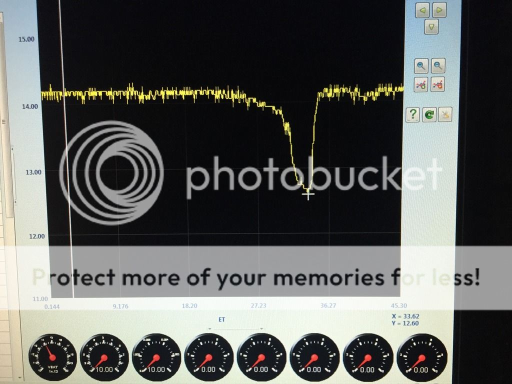
I took the car for a ride and eventually wound up at the same hill where I do my testing and logging. I did the same exact thing that produced the last few logs that showed the voltage drop. Once I got back to the house, I checked the log. Its FIXED! The minimum voltage was 14.18. Much better!

I still may upgrade to a 200A alternator. The way I figure, and since I have another core to use, it would cost me out of pocket significantly less than buying a 200A off the shelf. All I need is the remanufactured unit, an upgraded rectifier and an upgraded stator. Maybe a winter project once my bank account recovers!!!
In the meantime, I sourced an old stock 3G alternator, rusted from sitting in someone's shed, and one that was on a running car that is known good. I also still had my original in the car. Once the remanufactured alternator arrived, I had a total of four 3G alternators.
The remanufactured units don't come with a pulley. The two alternators that I sourced did have pulleys. One was stock, the other one is an underdrive. I also still have the stock one on the one in the car. I removed the stock pulley from the unit that was sitting in the shed. I cleaned it up the best I could and hit it with some self etching primer followed by some engine enamel. It was better than before, but didn't look all too great. I realized at this point that I was going to need a media blast cabinet to do some clean up work. More on that in another post!
I removed the stock 245k mile alternator again (I've had practice). I installed the pulley I had just painted on the Remanufactured unit and installed it in the car. That entire process took about 25 minutes. Next step was to take it for a ride and see if the voltage drop was still present. I started it up to make sure everything was working as expected and noticed the voltage gauge on the dash read higher than it usually does. This was a good sign! I shut the car down.
Next I boxed up the rusted old alternator as a core return, got the label on the box and brought it to the FedEx drop off. After it arrived at Rock Auto, they inspected it and returned to me the 75$ core charge. Nothing like getting 75 for an alternator that doesn't really work, is rusted and I don't know how many years old. This also meant that I was into the remanufactured Motorcraft that is installed in the car for 106$ total.
I took the car for a ride and eventually wound up at the same hill where I do my testing and logging. I did the same exact thing that produced the last few logs that showed the voltage drop. Once I got back to the house, I checked the log. Its FIXED! The minimum voltage was 14.18. Much better!

I still may upgrade to a 200A alternator. The way I figure, and since I have another core to use, it would cost me out of pocket significantly less than buying a 200A off the shelf. All I need is the remanufactured unit, an upgraded rectifier and an upgraded stator. Maybe a winter project once my bank account recovers!!!
Tuesday, June 21, 2016
94 Mustang GT: Voltage Drop, Alternator Harness Upgrade, PIP failure
Since I've been logging data with the Moates Quarterhorse, I've noticed a significant voltage drop between 4 and 6k RPM. Voltage drops from normal down to 12.6, which is just about battery voltage. If you open the hood of the car with out it running and test the battery, it will be 12.6v. With the car running, it is 14.4v.
So far, I have added an 8GA ground wire from the negative post to the factory ground location on the chassis. The 4GA ground from the negative terminal to the engine was not changed. I did clean the surface of the ground strap from the motor mount to the frame rail when I did the engine swap. The log looked the same.
Next, I thought maybe it's the battery. So I ran the same test / collected the log while using a 750A battery instead of the 525A stock battery. Same result, no change.
It has to be the alternator not being up to the task. Not surprising for a unit that was born in 1994 and has gone through two voltage regulators and one set of brushes. It was time to replace it! I ordered a motorcraft remanufactured unit from Rockauto.com.
It has to be the alternator not being up to the task. Not surprising for a unit that was born in 1994 and has gone through two voltage regulators and one set of brushes. It was time to replace it! I ordered a motorcraft remanufactured unit from Rockauto.com.
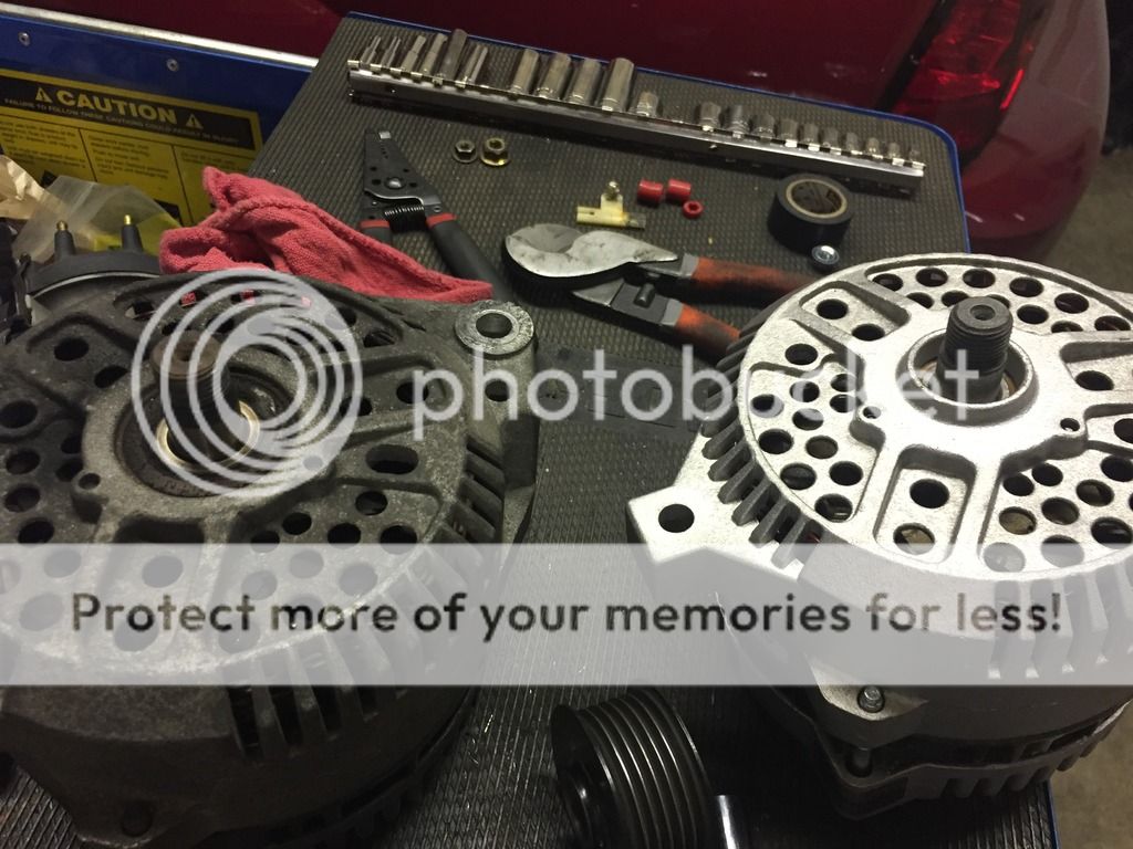
Normally, remanufactured units work really well. That’s typically because they are hand built and tested. The remanufactured alternator I received looked great at first, until I put the stocker and the reman unit side by side. Looks like someone used the incorrect front case when rebuilding the reman unit. I can’t get the pulley to sit right because it hits that shoulder on the case.

After a few emails, I shipped the ‘mis-boxed’ reman unit back to them with a label they provided and I should have the new reman unit tomorrow. Hopefully that one is correct!
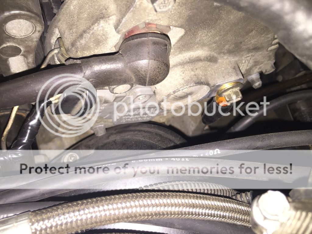
I did rebuild the stock alternator harness with a 4GA charge wire. I removed the stock harness - disconnect two plugs on the alternator and the charge wire, then the charge wire at the distribution block by the battery, the 4 pin plug, and the plug for the AC compressor. I disassembled the harness by removing the wires from the loom. Then I made a new 4GA charge wire, same length. I used a hydraulic crimping tool for the 4GA lugs (That hydraulic crimping tool works really well) and used heat shrink tubing. Then I added it to a new loom and wrapped it all in electrical tape. It really looks stock. I went one step further - On the back of the alternator is a bolt for the smog bracket. I cleaned up the surface area and ran a 4GA ground wire from the alternator case to the engine bay. It came out really nice!

I took it for a ride identical to the others to see if the graph is the same. I think that the hard drive protection kicked in on the laptop because I’m missing like 3 seconds of log file data, which ironically is 4k to about 6k RPM. You know, exactly where I need to see if the voltage drop is still there… That was Friday evening.
Saturday I took it out with intentions to run an errand with my wife and collect a new log. About 1/2 mile from my house the car stalls, barely starts and is running rough. I suspected the PIP sensor since the tach was jumping around. Ran back home (glad I had sneakers on!), grabbed my truck and trailer and got the car home – took a couple tries to get it onto the trailer due to no power / barely running. Got it back home and pulled the codes. Code 211 – profile ignition pick-up (PIP) sensor – circuit failure.
I suspect the Summit Racing street strip distributor has a failed PIP sensor (stator / pickup). The distributor has 7800 miles on it and is less than 1 year old. If it is the PIP I’ll know later today after swapping distributors for an MSD 8455 pro billet distributor I borrowed from a friend. I still have the stock distributor, and a brand new DU-50 Motorcraft pickup. Next steps will be depending on what Summit says about their failed product.
Thursday, May 26, 2016
94 GT : Push Start TFI vs TFI-ICCD
For some time now I've been chasing a random stumble. I eventually tracked it down to a misfire / ignition. I could see in the data logs that the RPM would drop, then catch up again. Shortly after that the wideband would show a lean condition. It turned out to be the TFI. I replaced it with a DY1077 motorcraft TFI (they no longer say motorcraft on them, but it is a ford part). Theres a bit of a story behind it though.
Some time ago the stock TFI failed. Car died, towed home wouldn't start. I had an old fox distributor with a working TFI, so I stuffed that in the fender, plugged in the TFI and it started right up. I removed the TFI from the stock distributor, modified it to fit and installed it with some dielectric grease. For a few years, the car ran just fine, so I didn't expect there to be an issue. I can only assume that the ignition demands of the new motor made the stumble present itself. Thats when I did some research. Long story short, the 86-93 Fox TFI are Push Start, and dwell is controlled by the TFI module alone. 94/95 are TFI-ICCD (increased computer controlled dwell) and the ECU will control a few additional parameters related to dwell (coil charging). When a Fox TFI is used in a 94/94, the ECU defaults to PIP to control dwell, which is very short. here is a great write up!
http://www.myo-p.com/Ford-EEC/EEC%20Help%20files/Files/TFI_grey_or_black.html
now the car runs awesome with the correct TFI installed. I'm also playing around with the spark tables. I found that adding an additional 2 degrees really didn't add to the performance / seat of the pants feel. But it wasn't pinging either. So when I needed fuel I used regular rather than premium, and it still runs awesome. I do have the fuel type set to 10% ethanol, so the calibration accounts for that.
Monday, May 16, 2016
94 Mustang GT: Moates Quarterhorse and Binary Editor - T4M2 by Decipha
Before I go any further, I want to give credit where credit is due. I have been absolutely devouring the knowledge base located at info.efidynotuning.com. efidynotuning.com is a site / forum created by decipha and it is an absolute wealth of knowledge on tuning efi. From that site I have downloaded the free T4M2 calibration and made the required changes as described on that page. For some reason I have yet to figure out, I'm not able get the car to a warm stable idle with that calibration. I believe my issue lies in the dashpot, as it seems that the bottom falls out as it idles down and just stalls. I know that it's not an issue with the T4M2 base calibration, because it is widely used. It's some value in the calibration that needs to change for my particular car / application. I'll eventually figure it out!
The T4M0 calibration works just fine. In that calibration I have the changes for the 90mm F150 MAF, the Siemens Deka 60lb / hr injectors and changes to cubic inches for the 306. I also made changes to turn off EGR and thermactor, and fan temps. Using T4M2 as a reference, and per the advice on efidynotuning.com, I have simplified the spark tables to use only borderline, scaled RPM and Load functions and increased spark by 6 degrees for the GT40 heads. I also made changes to the MAF transfer to start to dial in fuel by using Lambda - Lambse + KAMRF = Error %. In this calibration, perload is still inferred load and that will definitely need to change to perload = 0.
I'm going to start over with the T4M2 calibration / changes. Maybe there is something I missed or some typo thats causing me the grief with that calibration.
Wednesday, May 11, 2016
Jersey Shore Festival note to our Venom Crew!
Hello everyone!
The Jersey shore festival is going to be a great time. I grew up in Toms River and spent a good bit of time in Seaside growing up. I'll try and share some insights!
I know this goes without saying, please use your best judgement. I know from experience that Toms River and Seaside law enforcement has ZERO tolerance for shenanigans. Some of my friends that I grew up with work there, and they are good people! However, they won't hesitate to hand out a citation. This includes noise pollution from loud stereos! I'm sure it will be very crowded, so please stay alert! We don't want to make the news for any of the wrong reasons.
For those staying at the island beach motor lodge, Bum Rogers is just about across the street. The restaurant has decent food (there are better restaurants in the area if you're looking for an elegant dining experience) and the prices at the bar are reasonable.
PJ already mentioned the 7-11 that is close to the hotel. There's also a nicer CVS located near the bridge. Closer to Ortley beach (Ortley plaza) is an Acme grocery store and a spirits unlimited. Seaside liquors is another place to get your beer / wine / liquor.
The Saw Mill - I think we are all going to meet here at one point - has excellent pizza and food. There's also a bar here. Steaks unlimited and midway steak house are a few of my other favorites to get a bite. There are plenty of other places along the boards to grab some food on the run. I've had some of the best funnel cakes and zeppoles from places along the boards.
If you want to head into Toms River, there are a few places to mention. Naples pizza on Fisher Blvd has GREAT pizza / food. The Shop Rite on Fisher blvd is also really nice and would have anything you need. Across the street from Shop Rite is a car wash (I worked here at one point, they do good work!) and another spirits unlimited, with a pretty good selection and decent prices.
As I think of more, I'll get this updated!
Monday, May 2, 2016
94 Mustang GT: Ceramic Coated Headers
While doing the engine swap, new BBK ceramic coated headers were installed. When I pulled the stock motor, I already had some old style BBK Ceramic coated headers on the engine. They were shorties, and had been 'fixed' before I installed them years ago. When removing them from the stock motor I remembered how badly the individual flanges lined up with the exhaust ports. The new style headers have a solid flange which allows everything to line up nicely.
I also got into a discussion with Jet Hot Coatings http://www.jet-hot.com/ for a quote. Their customer service team was extremely helpful. So much that I'm going to share my experience. I went to the web site and entered my info to get the headers (with the individual flanges) coated. The quote led to prompt emails being exchanged. There is a fee to remove ceramic coating that is already on the headers. I REALLY wanted to have Jet Hot do the work. Their coatings have a lifetime warranty, and they don't just coat the outside, they do the inside as well! Nobody else does that. My decision to just buy new BBK ceramic headers came down to 1 thing. Those individual flanges were a pain to get lined up. I remember having pry bars and ratchet straps in use to get the bolt holes to line up properly. New headers wouldn't have that problem. I had to pass on the Jet Hot, because of this issue. My experience with them was awesome. And if I had a solid flange stainless set of headers, I would definitely have them do the work.
The BBK 15250 headers arrived and they are pretty! I also put together a set of header studs using stainless set screws and stainless nuts and lock washers. Once the gasket was installed, I installed the set screws and the header mounted right up with no hassle. I'm still bummed I couldn't go with the Jet Hot coating, but this will have to do for now!
94 Mustang GT: Siemens Deka 60lb/hr Injectors
With the new 90mm Mass Air in place, I decided to do some logging. The car felt really good during the drive, but I did see 102% Injector Duty Cycle. Now, we all know that the injectors cannot physically perform to 102% duty cycle, the ECU was commanding that. It's just showing that the injectors are maxed out.
I already mentioned that I will be installing the Siemens Deka 60lb/hr injectors, which have already arrived. Lightning Force Performance on eBay seemed to have a great price on these, which were about 300$ shipped to my door. I did install the injectors Friday night 4/29/2016, and learned something really important about the QH also. More on that in a minute.
Injector Install:
I first disconnected the fuel cutoff in the trunk and ran the car until it stalled. Then I removed the EGR tube, then all the plugs to the sensors in the upper intake - EGR, TPS and ISC. Then I removed the cold air to the throttle body and disconnected the cold air from the TB. I pulled all the bolts for the upper intake and removed the throttle and cruise cables from the TB and removed the TB bracket. There were two vac lines I had to disconnect - one for the Kirban FPR and one for the EGR. Then I was able to lift up the upper intake and remove the PCV / Vac lines from under the intake. I set the intake off to the side. I removed the fuel rail hold down bolts and lifted up the fuel rail, carefully, wiggling it as I lifted. The injectors popped out of the lower intake. One by one I removed an injector and installed the new one into the fuel rail with some motor oil on the O rings. I did not install them into the lower intake yet. Once all the injectors were replaced, I started towards the rear of the motor and pushed down, wiggling one by one until the injectors seated in the lower intake. Pushing down on the rail, I installed the bolts that hold the rail to the lower intake. The injectors were in.
After everything went back together, I had to drop the fuel pressure. I was running the fuel pressure high to try and compensate for the 19's not being enough. I turned the key on, loaded the template I created for the 60's, and the car started right up and idled just fine. Then I adjusted the fuel pressure.
I remember reading that if there is more than a 5% change to fuel, that the Keep Alive Memory should be reset. So I disconnected the ground on the battery and turned the headlights on. After 5 minutes I reconnected the ground. I tried to start the car, and nothing happened. It just cranked and cranked.
I realized something was wrong, but the only thing I did was reset the computer. I still had the laptop connected, so with the key on, I wrote the base calibration again. Then loaded the template for the mass air and updated. Then loaded the template for the 60s and updated. Then tried to start and it started right up and set into a nice idle. It was then that I realized that anything that gets 'updated' to the QH that is not part of the saved .BIN will get lost if the battery is ever disconnected. So any changes to the hardware in the car should be saved as part of the calibration. Not just updated using templates. Templates are good for 'try me' scenarios, but the saved calibration should include any calibration changes for upgrades / parts already installed.
The bung for the Innovate LC2 wideband is getting installed tonight. I'll do some data logging on the way to my buddy's house!
95 Mustang GT: Mass Air Upgrade and Quarterhorse Templates
As the days go by, I continue to learn. I also bought a license for EEC Analyzer (also created by Clint Garrity). I've learned what a template is and how to use it, which led me to kind of start over.
Here's what I did:
Load the T4M0 base calibration. This calibration NEVER CHANGES. Keep it as read only.
1. Make changes to turn off EGR and Thermactor (smog). Save as a template.
2. Increase cubic inches to 306. Change injector crank pulsewidth vs ECT by 306 vs 302 ratio and injector change ratio (19/19 so no change really) Save as a template.
3. Make changes to low and high speed fan temps for on and off. Save as a template.
This gets saved as my T4M0Base.
Today I'm driving to and from work and logging the entire time. I'll push those logs through EEC Analyzer to see what pops up. I already know that the stock 19s are not enough. Duty cycle is just too high. And the stock mass air is barely OK. I've already seen a 4.86v reading, which means it's REAL close to being pegged. That being said - read on for the beauty of the Quarterhorse!
Mass Air sensor:
I bought from eBay a stock 2004 5.4L F150 Mass Air meter. It's basically the LMAF 90mm mass air meter, but not for the lightning. There is a KNOWN mass air transfer curve for this particular meter (sensor and housing). Shipped to my door it was 25$. Thats right - a 90mm Ford mass air meter for 25$ shipped. I had to buy some bigger 3.5 inch couplers (20$) and the correct mounting flange for an 03 F150 (15$) to get it installed with my cold air kit, and Sensor plug (I bought the original ford F150 plug for 24$ shipped). I made an adapter to go from that mass air sensor chassis side plug to the mass air harness so it will look factory. So for 85$ I can install this sensor, update the MAF transfer curve in the QH (already have a template for it) and eventually dial it in. The known curve should make it a breeze.
Installing the Mass Air:
First step was to pull out everything from the stock mass air going into the fender and get it on the bench. I then had to cut off the stock flange from the elbow that goes into the fenderwell. This wasn't as bad as I thought it would be. I just needed to leave a 1 inch lip in case I needed to revert back to stock. Then I started putting together the new setup. I realized that the bolts for the stock meter to stock flange were too big and wouldn't work. Off to the hardware store for nuts and bolts. Came back and bolted the sensor to the adapter flange, added the coupler to the elbow and put that in the fender. Then the other coupler to the tube that goes to the throttle body. Then I removed the stock mass air and ACT sensor harness. I removed the pins from the chassis side harness and installed the pins for my adapter. Then I plugged in the stock F150 Mass Air harness. Plugged everthing in, tightened down all the couplers once it was all aligned, and installed the filter in the fenderwell. I then fired up the quarterhorse, loaded the template for the mass air and updated, and it started right up and settled into a nice idle. Now I have a very nice setup with the 90mm mass air.
Injectors:
For my mild 306 I'll be installing Siemens Deka 60lb/hr injectors. These are the same injectors that are sold as ford racing, except the ones I bought from lightning force performance have the jetronic connector, not the (new) USCAR. So they should plug right in. I know - first thought is - "thats way too much injector for that setup". I thought the same thing too. Again, the beauty of the QH is that there are only a few parameters to change, and they are published for the injectors: high slope, low slope, breakpoint and voltage offset. The injector crank pulsewidth also needs to be adjusted by the ratio of 19's to 60s. I already created the template for this as well. These new style injectors are very tame at the low slope and shouldn't cause problems with 'dumping' fuel at low RPM / idle. They should run like stock but at a MUCH less duty cycle. The best part - no more buying new injectors if I ever want to upgrade! These will support any application / upgrade I come up with - right up to block splitting HP (and beyond). to put it in perspective, I almost bought the 80lb/hr injectors, but just couldn't swing the extra cost right now.
94 Mustang GT: Moates Quarterhorse and Binary Editor Beginnings
The Quarterhorse arrived in the mail two days after I ordered it.
Current Configuration: 1994 Mustang GT Convertible, 306CI GT40 Heads, 1.72 scorpion rockers, FTI cam, 94 Cobra Intake, BBK 70mm TB and stock injectors / mass air.
I downloaded and installed BE on my laptop. I eventually needed to plug in the dongle which I paid extra for. The dongle is essentially a portable license. I then plugged in the quarterhorse and had to install the drivers via device manager. This was all done while sitting on my couch - QH was not yet plugged into the car. I then updated BE and downloaded all the latest strategies and calibrations (I learned later I only need two of these... ).
I downloaded the CBAZA strategy and opened that in BE. I then needed to know what computer was in the car. Pulled the passenger kick panel to reveal it is a T4M0. Downloaded the stock T4M0.bin and wrote that to the QH. This gives me a BONE stock calibration.
Next I pulled the ECU only to reveal that there is a hypertech chip installed! I've had the car for years and I never knew that. Apparently it isn't compatible with an MCRP prepped 306 with an Ed Curtis cam! It certainly wasn't running correctly. Anyway, I pulled the chip, installed the QH and plugged it into my laptop. I was still able to 'see' the QH.
I disconnected the negative battery terminal and turned on the headlights to erase any Keep Alive Memory and adaptive learning. After a few minutes I connected the battery and started the car. It ran, and ran much nicer than previous. I hit the data logging start button and like magic I'm getting all these interesting readings from the QH - so I know it is working with the ECU. I shut the car off and happily went on with my evening.
Then I started reading. One thing that is nice is that this is not a new product / process. People have been using the QH and BE for YEARS, which means there is a ton of info out there. The best resources so far have been EECAnalyzer.net and the forum there, and Efidynotuning.com for the write ups.
Now I started playing around with the stock calibration. I made changes for the cubic inches to increase to 306. I also made a change to the fuel since I'm running 93 octane with 10% ethanol. I then wrote that to the QH, Started the car and took it for a drive to do some data logging.
My main concern was the stock 19 injectors (serviced and flow matched by Accurate IS) and the stock mass air. Will I peg the meter? will the injectors be enough? all the math pointed to the answer of maybe but it was all borderline. I now had the opportunity to take the car for a drive and data log a WOT pull. The pull felt pretty good but it was choppy from 4k to 6k RPM. What I found was REALLY INTERESTING!
Fast forward to me on the couch again looking at the data log. The first thing I learned is that large data logs are a pain to deal with. I copied the data from the WOT pull timeframe from the huge data log (.csv file) and made a new .csv via excel - essentially a new data log file. Now looking at this one is much more granular. Here is what I learned by looking at the log.
1. Air Charge Temp (ACT) was 40 degrees. It was very cold out!
2. At about 6k RPM the Mass Airflow Sensor Voltage (MAFV) is 4.81. to peg it will be 4.9 or higher for an extended period of time. Its CLOSE, but not pegged.
3. Injector duty cycle (INJDC1 and INJDC2) is 97%. This has me concerned. more on this in a minute.
4. Battery voltage (BATV) drops a LOT during a WOT pull. Battery and charging system are good, but the volts dropped from a healthy 14+ to 12.08 (min value) during the pull. I would have never known!
5. The ECU demanded a 11.8 AFR (LAMBSE1 and 2) during WOT. There was no correction happening, so I know MAF curve is good (it should be, since this is a stock calibration).
6. RPM is very smooth up until 4500. From there to 6k it seems to be 'choppy' (peaks and valleys in the graph). I'm not exactly sure what this is from, but I have some ideas.
7. ECU gave just about 27 degrees total timing at 6k. This was also interesting. I know from the dyno break in of the engine that it wants about 30 degrees to make the most power.
8. I can no longer own a mustang without having access to the data that is provided by a tuning device. It will be SO EASY to troubleshoot a problem with this thing.
Next steps:
I ordered a Kirban AFPR. I'm going to increase the fuel pressure, which should keep the duty cycle of the injectors down. Mass Air isn't pegged, so I'm going to leave that for now (although I do have a REALLY NEAT plan worked out to upgrade that in the future). I'm also going to clean up the ground wires to the engine / chassis / battery. I still can't believe how much that battery voltage dropped, and the choppy RPMs up top could be ignition related. It certainly isn't fuel or air after seeing the log.
Some important things I learned from reading - for you forced induction folks - The calibration I'm working with scales to 100% load. There are FREE calibrations that go to 200% load. An NA motor will never see over 100% load, but a power adder will take the load into the 100%+ range. The QH easily accounts for that!
An innovate wideband will plug right into the laptop (I need 3 USB ports though - QH, Dongle, Innovate) and will be logged along with the data from the QH. That means the data log graph would not only include the LAMBSE (what the ECU is demanding) but also the LAMBDA from the wideband which will show what the engine is producing in the exhaust. Once LAMBSE = LAMBDA, Fuel and Air are dialed in perfectly. THAT is why tuning with a wideband is so important for modified engines.
My engine is not 'highly' modified. Its built to be a VERY stout daily driver. But by the time I'm done with this effort, its going to be a very fine tuned application! More to come as I make more progress!
94 Mustang GT Convertible: Engine and Trans Upgrade
Here are my notes from the engine swap. It kind of covers what I went through on a day to day basis. The plan was to take a week off work, pull the T5, get it to Hanlon for a rebuild, pull the engine and get the new engine installed. It was a great plan, but didn't really play out that way.
First step was disassembly and actually getting the engine and trans out of the car. Here are some notes on that.
Start 2/8/2016
Disconnect the fuel shut off switch
Run the car until it stalls
Crank the car a few more times
Disconnect and remove the battery - keep it on a tender
Remove the mid pipe
Remove the driveshaft
Remove the shifter, speedo, reverse
Remove the crossmember and transmission
Take the trans to have it rebuilt at Hanlon Motorsports 2/10
Drain coolant, remove radiator
remove cold air intake
unbolt the power steering bracket and keep it off to the side.
remove upper intake - throttle cable, vac lines, EGR tube
Unplug EVERYTHING - there’s a lot
Motor mount bolts
ground strap and starter wire loom (3 spots)
engine out 2/12/2016
Trans - dropped off 2/10/2016 to Hanlon motorsports. The rebuild took just under 3 weeks time, but was totally worth it.
Got trans back 2/28/2016 - fixed cancer on main shaft, cluster support brace, latest rebuild kit, new fork and pivot ball.
Now that I had the trans back, There were some things needed. I made a list and then marked them off with the word done once it was taken care of.
Done Vacuum line 3/8 and 1/4. This was for the fuel pressure regulator, bypassing the smog vac lines and new hose for the PCV.
Before engine install
Done - Wire loom repair. Some broke / cracked during the extraction of the engine.
Done - install bell housing, new clutch fork, new release bearing
Done - replace pivot ball - the stock one was cone rather than a dome from all the wear.
Done - Restore dipstick tube. Stripped, painted with etching primer and then black wrinkle.
Done - Install dipstick along with some black RTV to prevent leaking
done - rust on the framerails - how far does it go? This was way worse than I thought it was. We cut holes in the frame rails and knocked out as much rust as possible. Then needed to do some rehab to stop the rust.
Done - Rust rehab in the framerails - wire brush, degreaser, metal prep, POR15
Done- Create cardboard frame rail templates - there will be an inner plate (11GA steel) and an outer plate that goes over that.
Done create frame rail plates 11 gauge 1/8 inch steel from templates. Inner and outer both sides.
Done test fit frame rail plates
Done paint frame rail plates with weld through primer.
Done - Lou - weld in frame rail plates - inner and outer. Some additional cutting , bending , shaping.
Done - wire wheel plates / welds
Done self etching primer the plates
Done black wrinkle over primer.
Some work on the engine while it was on the engine stand.
Done - New bbk ceramic unequal headers and header studs.
done - tighten header bolts
Done - Upper intake bolts - trim? No
Done - Distributer install
Done - install EGR on upper intake.
done - install passenger side VC vent tube
Done - install TB.
done - clearance intake - make it fit without spacer. This was achieved by changing the pvc fitting on the upper plenum (in the back) with a plastic one that had a lower profile. Also had to grind away some of the TB mounting flange on the back side. Then the intake fit without a spacer!
done - make EGR block plate
Done - trans prep - install crossmember, rebuild shifter, install vss, add fluid (Dex III Merc, non synthetic), install shifter.
Finally time for Reassembly
Done break out the crane!
Done Install motor mounts and motor once on the crane
Done install motor 3/7/2016 it is in the car.
Done PS bracket
Done coil install
Done Engine electrical hookups
Done Trans install
Done Shifter handle, boot and knob
Done Coolant lines
Done Fuel lines
Done Radiator and overflow
3/8/2016
Done Starter and bolts
Done Cap and wires
Done Idler pulley
Done Motor mount nuts
Done Driveshaft
Done mid pipe and O2 sensors
Done grounding straps
Done Upper intake, electrical, vac lines
Done EGR tube install on header (with Penny) - this was removed later.
Done Cold air intake
Done validate belt routing
3/11/2016
Done Fuel shut off
Done Battery
Done Coolant
Done power steering fluid
First startup - prime 2x pull spout
3/12/2016 it runs (rough). It was late so I didn't run it for long.
3/13/2016 Set the Timing at 10 degrees with the spout out.
Throttle body adjustment - base idle reset.
Adjust clutch cable - too tight. Needed to take out the MM 3/4 spacer at the end of the cable where it meets the clutch fork.
I'm having problems with it staying running. I did get the timing set and made a mess of the coolant. trying to burp the system. Pulled the codes and got one for the ECT. Off to the store we go. To pick up fuel pressure gauge (rented), IAC, ECT, and a belt.
3/14 - Lou showed up to help out! pulled plugs - fouled. codes say engine coolant temp sensor is bad. fuel pressure is good. belt is too short. Back to autozone to pick up plugs and exchange the belt. When we got back we replaced belt it fit well. We replaced plugs, and did another idle base reset. Unplugged the ECT from the car and plugged in new ECT - not installed, but It idles (cold)!
3/16 Installed ECT and added more antifreeze. Idle set at cold and hot.
3/19 Its finally down off jack stands, and I got a chance to ckear out the garage. Test drive led to CEL - multiple.
3/20 - CEL for lean exhaust. Fixed exhaust leak - #4 header tube passenger side. I loosened header, tightened #4 and the rest. Also moved shim on k member for mid pipe clearance. firewall adjuster is all the way in - still tight. I also found muffler is cracked. Removed spacer from MM clutch cable at the quadrant. adjusted firewall adjuster - clutch feel is perfect now.
3/22 - Cleared codes and drove it. Multiple codes point to CCRM (fan low speed, fuel pump relay). Replaced. Codes are gone for CCRM. I must have kicked the CCRM I don't know how many times getting into and out of the engine bay when doing the rust rehab.
3/24 - Replaced O2 sensors. Cleared memory and drove it. CEL again.
3/25 - Still getting lean code. Fixed header collector flange leak on drivers side. Installed new stainless studs, nuts and washers. Cleared memory and drove it again. Still getting CEL.
3/27 - Lean code still there. Also suspect fuel issue. Traced wires. Found that power to ground pin on the engine harness side for the drivers side O2 sensor connector is pushed back. Serviced by taking weather pack apart and moving the pin then putting it back together. No more lean code 176! Found fuel on the intake. #1 injector popped out. loosened fuel rail, pushed injector back in, held down fuel rail and tightened. At this point, I also ordered the Moates Quarterhorse package and Binary Editor.
Thursday, March 10, 2016
Gypsy Moth
The Gypsy Moths are coming! I live in Saylorsburg, PA and we have an infestation here. I'm trying to help us all out. If we all chip in, this will help!
Here is an inexpensive Do-It-Yourself way to make a barrier band for trees. Wrap the trunk in duct tape - shiny side outward, sticky side toward the tree about chest height. Maybe two times around yielding a 4 inch wide strip. Then smear on petroleum jelly using a disposable plastic butter knife. This should be 2 inches wide, about 1/8 thick, and more toward the top of the band to allow for drip down.
Thats it!
Here is where the info came from:
DIY Sticky Barrier Band
http://fyi.uwex.edu/gypsymothinwisconsin/making-a-sticky-barrier-band/
More info on barrier bands.
http://www.nj.gov/agriculture/divisions/pi/pdf/GMBarrierBands.pdf
Make sure to check the bands every couple days to make sure the petroleum jelly is not dripping down onto the bark. you can clean this up with a paper towel if it does start to drip. Also make sure that the barrier band is not clogged with insects.
Good luck this season!
Subscribe to:
Posts (Atom)